Wednesday, July 15, 2015

Ski Press: Steel

In October of last year my friend Matt came to me and said that he was interested in custom built snowboards for some of his buddies. I explained that my current ski press was not wide enough to accommodate a snowboard.  We quickly got to talking about what it would take to build a snowboard and he promised funding to help me build a new ski press.  I began looking for steel on Craig's List and eBay, hoping to find exactly what I needed. In the mean time, I completed a few calculations to scope out the beams that I might need to build a wider ski press.  After only a  few weeks I found a guy offering both steel beams and square tube in really good shape.  Based on the steel available I came up with the design shown below. The design is based on pin joints.  Pin joints cannot transmit a moment and therefore the number and size of bolts needed is minimized (i.e., one per joint).  This also meant the amount of drilling I had to complete was minimized while maintaining a robust design.  Each pin is made from a 7/8" diameter grade 8 bolt.  For comparison, a four bolt joint would require four 3/4 inch bolts to handle the moment load. The design is based on four W10x49 wide flange beams, 6x6 half inch thick square tube cross beams, and 5x5 half inch thick square tube vertical beams.
Some of the calculations I completed to show that this press would have enough strength are below.  Despite the seemingly giant size of the beams, it turned out that they were just adequate to meet my minimum safety factor. I desired a safety factor of 3 at a design pressure of 50 psi.  Over the 20" width and 84" length of the press, this results in a load of 84000 lb or 42 tons. For comparison, this is the equivalent weight of 7 adult male African elephants or 25.5 Corvettes.


My other buddy Shane knew the owner of Olson Landsaping and so he offered to help us pick up the steel with his 5 ton dump truck.  The total weight of the steel ended up around 2500 lb; I purchased all the steel for $400.  The wide flange beams were 18' long so we used a torch to cut them in half on site.  Each of the four beams had a final weight of 441 lb.


The 5x5 square tube also had to be cut in half for transport.  We attempted to cut it with the torch, but ran out of fuel before completing the cut.  Fortunately, the facility had a bandsaw that we used to cut the tube.


After a 45 minute drive home, we unloaded the steel and moved it to the garage.  We had a fork lift to help us load the steel at the site, but at my home we only had four guys. Therefore, we dumped the beams on the driveway and manhandled them into the garage. Needless to say, I was no longer going to be parking a car in the garage.


The first major step was to cut the square tube to length.  I have limited resources, but Olson Landscaping supplied us with a gas powered cement saw.  I purchased some 14" diameter cutoff wheels and we cut the beams to size.  The biggest trick with this was to get the cut started.  The high speed and large diameter of the wheel caused it to bounce and flex until we got deep enough into the steel.
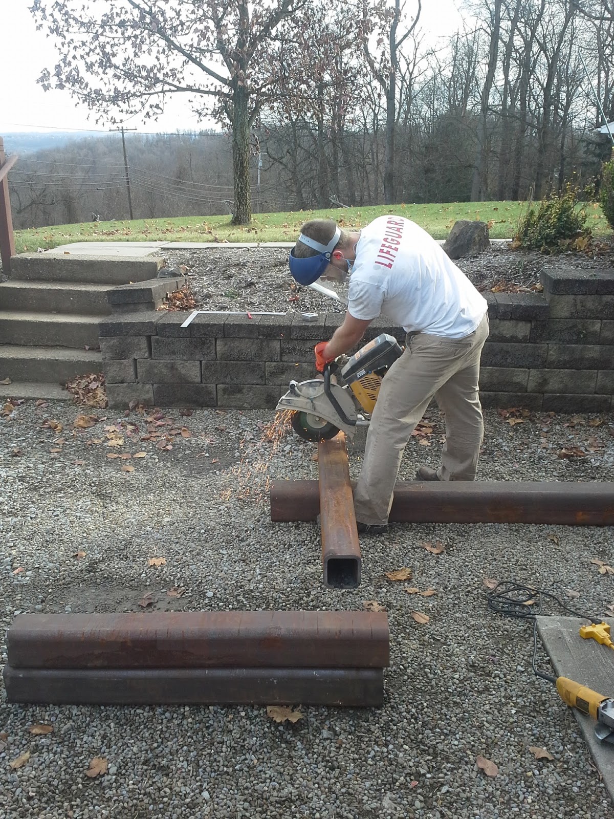


After cutting the beams to length, we needed to notch each of the four 6x6 cross beams so that the 5x5 vertical beams would mate up.  We used a 4.5" diameter cut off wheel and angle grinder to make these cuts.

In order to drill the holes necessary to connect the beams and have them be reasonably accurate, I co-drilled the two holes in the beam.  I did this by centering the hole with a small center drill and then used a long 1/4 inch drill bit to drill through both sided of the beam.  The holes in all the beams were mapped with the same template so that they would be as accurate as possible.


Stepping up the holes to 7/8" diameter proved to be a bit more difficult. My bench top drill press had a minimum speed of 600 rpm, but I needed to slow it down to 300 rpm to keep the larger drill bits from chattering.  I did that by building the speed reducer shown below.


My bench top drill press also has limited horsepower.  To complete the holes I couldn't just start with a 7/8 drill bit, but had to step them up.  I finished the holes 1/32 oversize using a 29/32 drill bit.  The sequence of drilling I used was:
  1. 1/4 inch center drill
  2. 1/4 inch short drill bit
  3. 1/4 inch long drill bit
  4. 1/2 inch drill bit
  5. 5/8 drill bit
  6. 3/4 drill bit
  7. 7/8 drill bit
  8. 29/32 drill bit

 This sequence was completed for all 32 holes. It took some time, but with a cup of oil and a paintbrush we kept the drill bits cool and I only had to sharpen the 7/8 drill bit once.


Once the holes were drilled, I had to drill and tap four 5/16-18 holes to connect the wide flange beams to the cross beams.  As with the other holes, I made a template so that each cross beam was identical.  The drill press was used to complete the holes and each was hand tapped.


Mating holes were then drilled in the wide flange beams.  In this case, I couldn't clamp the beams to the drill press as they were too heavy.  Instead I moved the drill press to each of the sixteen hole locations.


I used a sanding wheel on my angle grinder to debur all the holes and then it was time to begin the assembly.  I purchased all my fasteners from McMaster Carr Supply Company.


The image below shows the 7/8" x 9 inch long bolts next to the 5/16 bolt used to hold up the beam.  Note that the 5/16 bolt does not see load in service and only suspends the beam. Each beam has four bolts and will only see 110 lb of load.

The image below shows the test fit-up of the braces; each brace has a weight of around 400 lb.  The braces did go together the first time and none of the holes had to be tweaked. This is something of a miracle considering my rudimentary machining methods.


From this point, the rest of the press could be assembled.  Note that the bolts stick out about three inches beyond the brace. This was done on purpose to ensure that only the shank of the bolt would see the bearing load due to the pressure.  Loading on the threads would not be good for the bolt or braces.


A couple of jacks and some serious manpower was used to assemble the press. My original idea was to disassemble the press after test fit-up, wire brush it, and then paint it.  After experiencing the amount of work to assemble it, I decided that the no-paint industrial look was more than adequate.

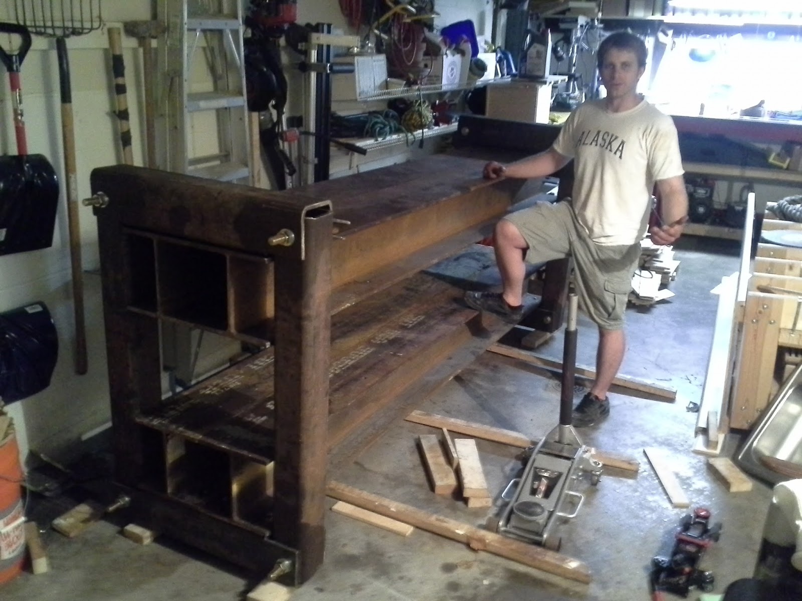


At this point the basic frame of the press is complete, but I still have to put the press on wheels, build a second air bladder, assemble my pressure regulating system, mount a working surface (MDF) to the press, and build a "ladder" to ensure even pressure distribution from the two air bladders.

Saturday, March 7, 2015

Graphics and Final Details

It's been a slow ski-building season but I finally finished the Aftermath 3.0 in early February. My sister again helped me with the graphics.  I had wanted to do a printed graphic, but realized that the dark basalt layer would wash out a printed graphic, so we used acrylic paints again this year.

The goal of the graphic was to tie basalt into the design while keeping with the Aftermath theme.  Basalt is formed by the rapid cooling of lava and can form a hexagonal crystal structure.  As a follow up to last years Revelation theme, a red dragon eye was used (vice last years white horse eye).  Here are a few photos that show the development of the graphic.


At this point all the layers of the ski were nearly ready.  The quad-axial basalt  was cut into strips for the layup.


This pair of skis are the last planned use of the wooden ski press.  My goal for next year is to have the steel press ready; this will allow me to press two skis at once or even a snowboard.


I cut the flashing off again this year with a jig-saw which isn't ideal.  The blade angle can change during cutting and produce an edge that is not perpendicular to the base.  Next year I hope to have a bandsaw.  This year I built myself a spindle sander from an old air compressor motor so that I could more easily finish the ski edges, tip, and tail.  I used a 6" diameter expander wheel and sanding belt for the spindle.  The sander worked very well, especially compared to the belt sander I had used in years past.  During edge sanding it never bogged down and I didn't even have to change the belt.  This turned out to be a very good investment.


The final ski is below; I didn't use tip or tail spacer material this year, but ran the core the full length of the ski.  I did cut the core about 5mm narrower than the tip and tail so that no wood would be exposed; this is shown below.


Overall, the skis have a good flex and a relatively low weight; they are the heaviest of the Aftermath, but also have the best overall flex. A summary of the three generations of Aftermath is shown below:


Stiffness (lb/in)
Pair Weight
Aftermath (AMH-12)
17.34
8 lb 10 oz (3912 grams)
Aftermath 2.0 (AMH-13)
7.95
7 lb 0 oz (3175 grams)
Aftermath 3.0 (AMR-14
12.22
9 lb 0 oz (4082 grams)


Sunday, November 23, 2014

All Mountain Radacoski (AMR-14)

It's been a busy year, but I am currently making a pair of skis for a friend, Matt Radacosky.  I am also in the process of building a new ski press from steel, but will post about that later. This year I am making a pair of eastern all mountain/freeride skis similar to the Aftermath of last year, but wider.  The aftermath is 127-88-109, 53% of the ski is in front of center, and has a turn radius of 17.7m.  The AMR-14 is 128-100-118, 51% of the ski is in front of center, and has a turn radius of 19.9m.  You can see the difference between the skis below.


I am also going with a sidewall design this year rather than the cap design.  I expect the ski to be a little heavier, but should be more responsive in turns. One change I am making this year is using a basalt fiber instead of fiberglass - basalt is made from igneous rock. Here is some info about basalt:

Basalt fiber is a material made from extremely fine fibers of basalt, which is composed of the minerals plagioclase, pyroxene, and olivine. It is similar to carbon fiber and fiberglass, having better physicomechanical properties than fiberglass, but being significantly cheaper than carbon fiber. (http://en.wikipedia.org/wiki/Basalt_fiber)

...the basalt/epoxy sample's strength tested 13.7 percent higher than that of the E-glass sample and exhibited 17.5 percent greater stiffness, although the basalt sample was 3.6 percent heavier than the E-glass sample. Additionally, basalt fibers are naturally resistant to ultraviolet (UV) and high-energy electromagnetic radiation, maintain their properties in cold temperatures, and provides better acid resistance. (http://www.compositesworld.com/articles/basalt-fibers-alternative-to-glass)

 Relative tensile strengths (breaking strength) are listed below:

Steel                  73000 psi  (0.50 GPa)
E-glass            500000 psi  (3.45 GPa)
Basalt              600000 psi  (4.15 GPa)
Carbon Fiber   725000 psi  (5.00 GPa)


After some extensive searching, I found some quad-axial basalt fabric from a company in Germany -iXperial (http://www.ixperial.net/). I highly recommend them; this shipment was fast and the customer service was excellent. Most fiberglass in skis is tri-axial, meaning that it is layered along three axes.  The basalt fiber I ordered is layerd on four.  The basalt will be visible through the topsheet and graphics layer.


This year I purchased a new 2.5HP router and a 6 Amp jig saw.  If I could afford a large bandsaw I'd have one.  The extra power in these tools over my past tools makes a big difference in cutting time and surface finish.  The core of the ski is nearly identical to the Aftermath, but substitutes pine for the cedar.  It still uses 3 oak stringers, 5mm wide, along with Aspen and Poplar. Photos of the core in process are below.


The base material is simlilar to last year and is a 4001 grade sintered P-Tex. This year I was able to get the base template and core member template printed on the same sheet, which saved some time and money.  The base in process is below.


I did run into a problem this year; after I cut out the base and superglued on the edges, I realized that one base had warped out of shape.  I have speculated that it had something to do with internal stresses in the base material.  When the material was cut, the stresses were relieved and it warped.  It's common in steel and I have seen it in plastic tubing before.  I had to re-order the base material and try again.  This time I cut out the base roughly at first, leaving about 1 inch to the template.  I then took a second pass using the template and it turned out fine.

I am returning to the sidewall design again this year.  The following pictures illustrate attaching the sidewalls to the core, planing the core, and profiling the core.


My friends Matt and Shane;  Shane is determined to make skis with me for a living; I forced them both to wear hearing protection.


Once the skis were profiled, I used my belt sander and 50 grit sand paper to smooth out the surface after routing. One thing I was worried about, after my last experience with sidewalls, was getting the sidewall to stick to the epoxy.  Ideally, the plastic surface would be very rough with a surface finish that looks like that of the base material.  The 50 grit belt seemed to do the job quite well as shown below.  The surface looks like it does when it is abraded at the factory. This will give the epoxy "hairs" to grab onto as it forms a mechanical bond.  A lesser grit would produce a cleaner looking surface, but would not bond as well.


The next step is to finish the graphics layer, prep the top sheet and basalt layers, and press the skis.
 
Here is a preview of the new ski press.