Monday, January 30, 2017

Mounting Marker Tour Bindings

The thing about skiing the "backcountry" in Pennsylvania is that we don't get a lot of snow.  The highest snow regions in PA average around 150 inches per year (Laurel Highlands) and the Pittsburgh region is much less, around 40 inches if we're lucky.  This means that for "sidecountry" or "urban backcountry" skiing, I need to take out my rock skis.  For this I have relied heavily on my original prototype Goliath skis which have traditional alpine bindings.  I finally found a pair of affordable Marker Tour F10 bindings and decided to mount them on the Goliaths.

The great thing about Marker Duke, Baron, and Tour bindings is that they come with an adhesive mounting template as shown below.


The mounting template gives you the boot/binding center for a range of boot sole lengths, so once you know your boot length you can line up the center of the template as necessary.  At this point you should already have the proper Small or Large binding depending on your boot size.  When finding the boot center location on the ski you have to make sure that the new pilot holes are not too close to past drill holes or you could tear out a screw or weaken the ski too much.  Once you have mounted your template you will need to drill the holes.

Marker recommends a 9.5 mm deep hole with an unspecified diameter.  A little internet research will point you to a 3.5mm or 3.6mm diameter bit unless you have a metal topsheet in which case a 4.1mm bit is recommended.  In typical frugal engineer fashion, instead of buying a bit I decided to use a bit I had; 3.6mm is equal to 0.142 inches which is remarkably close to a 9/64 inch bit (0.141in).  To get the 9.5mm depth I taped off the drill bit as shown below.  Drill the five holes for the toe and four holes for the heel of each binding using the proper Small or Large pattern.


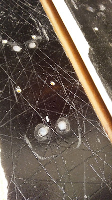
 Once complete, I filled the old holes with a two part epoxy to ensure that water would not get down into the core.


 Prior to mounting the bindings, I filled each drill hole with a water resistant wood glue; epoxy will do the same job.  The glue simply seals water out of the hole and helps keep the screw in place over time.  You can mount the toe or heel part of the binding first, it doesn't matter.  Just make sure the release mechanism operates properly once you've got it mounted.  To install the toe screws you will have to have the binding in the engaged position for some and touring position for others.


 Once the bindings are mounted you will have to adjust the binding properly for you boot.  This is where I'm supposed to recommend you have this done at your local ski shop so they can properly test release of the boot. However, if you choose to do it yourself, Marker provides instructions.  The DIN setting is simple; the toe piece (on the side) and heel piece (just behind the red indicator gage) each have a screw that adjusts the spring tension.  There are many DIN calculators online.

Once the DIN is set you will want to adjust the toe plate.  The Marker Duke, Baron, and Tour toe plates are adjustable to fit alpine or touring bindings.  This is adjusted with a screw at the front of the toe piece as shown below.  Marker provides a nice gage to ensure the toe piece is adjusted correctly. Simply place the folded gage between the boot and binding.  adjust the gap until you can pull the gage out and expose the green check mark and not the red x.  If you cannot pull it out at all, then it is too tight.


Finally, you will need to adjust the heel piece.  This can be done when the boot is locked into the binding.  Adjust the screw until it is flush with the binding as shown below.  Make sure to release and lock the boot again to verify.


 I am really looking forward to taking these new bindings out for a test run when PA finally gets some snow this year.


Saturday, October 3, 2015

Ski Press: Steel - Peripherals

Dollies:

To mobilize the ski press, I purchased eight 330lb rated swivel caster wheels and built two dollies with four caster wheels each.  The dolly frame was built from 2x8 lumber that I had left over from my deck. One dolly is situated under each brace of the ski press.


I used a jack and blocks to raise the ski press up and onto the dollies.


Air Bladder:

Since this ski press is double the width of my old press, I had to build a second air bladder.  To do this I purchased 6" diameter lay flat discharge hose (60psi max) from McMaster-Carr Supply. The hose is roughly 9.5" wide when it lays flat.  I also purchased angle iron, 5/16 cap screws, nuts, and washers.  These are used to secure each end of the air bladder. Five holes were drilled through the angle iron and discharge hose to facilitate the screws.


 I purchased a through-wall fitting in order to attach the air supply.  I made washers for the fitting from 1/16" thick EPDM rubber.  A generous amount of silicone calk was used around the fitting and inside the hose at the ends to create an air tight seal.


I cut four small pieces of angle iron to link the old and new air bladder together. I then attached two air hoses to a manifold along with a pressure gauge and ball valve.


Ladder:

I built a ladder in order to evenly distribute the pressure from the two air bladders.  The ladder consists of  88 cross members made from lumber cut to 1" square by 22" long. I then drilled holes in each side of the cross members.  The cross members were strung together with 1/16" steel cable; a spring was added to each end of the cable to allow the ladder to flex along the length of the ski.  Square aluminum tube would be more ideal for this job, but would have been expensive (88 x 22"= 1936" = 161.3 ft, roughly $630 vs. $20 for the lumber) not to mention more time consuming to machine.


Work Surface:

I built a work surface for the compression side of the press so that I could easily slide the ski and mold in and out.  I used 3/4" inch MDF for the surface which I later finished with three coats of polyurethane.


Using three hinges I attached a fold-up work platform to the side of the press that I plan to use for layup of the skis.  This is ideal since my space is limited.


Work Bench:

I built a work bench/shelf to store my ski supplies.  The bench has a 6" wide raised platform on the backside which can be used to attach ski edges to the base.  The bench top is attached with three hinges that allows it to be opened; the opened bench serves as a waxing station which will collect all the dripped and shaved wax.

 
It doesn't look like I'll get to use the ski press for this ski season, but I have several ski designs planned for next season.


Wednesday, July 15, 2015

Ski Press: Steel

In October of last year my friend Matt came to me and said that he was interested in custom built snowboards for some of his buddies. I explained that my current ski press was not wide enough to accommodate a snowboard.  We quickly got to talking about what it would take to build a snowboard and he promised funding to help me build a new ski press.  I began looking for steel on Craig's List and eBay, hoping to find exactly what I needed. In the mean time, I completed a few calculations to scope out the beams that I might need to build a wider ski press.  After only a  few weeks I found a guy offering both steel beams and square tube in really good shape.  Based on the steel available I came up with the design shown below. The design is based on pin joints.  Pin joints cannot transmit a moment and therefore the number and size of bolts needed is minimized (i.e., one per joint).  This also meant the amount of drilling I had to complete was minimized while maintaining a robust design.  Each pin is made from a 7/8" diameter grade 8 bolt.  For comparison, a four bolt joint would require four 3/4 inch bolts to handle the moment load. The design is based on four W10x49 wide flange beams, 6x6 half inch thick square tube cross beams, and 5x5 half inch thick square tube vertical beams.
Some of the calculations I completed to show that this press would have enough strength are below.  Despite the seemingly giant size of the beams, it turned out that they were just adequate to meet my minimum safety factor. I desired a safety factor of 3 at a design pressure of 50 psi.  Over the 20" width and 84" length of the press, this results in a load of 84000 lb or 42 tons. For comparison, this is the equivalent weight of 7 adult male African elephants or 25.5 Corvettes.


My other buddy Shane knew the owner of Olson Landsaping and so he offered to help us pick up the steel with his 5 ton dump truck.  The total weight of the steel ended up around 2500 lb; I purchased all the steel for $400.  The wide flange beams were 18' long so we used a torch to cut them in half on site.  Each of the four beams had a final weight of 441 lb.


The 5x5 square tube also had to be cut in half for transport.  We attempted to cut it with the torch, but ran out of fuel before completing the cut.  Fortunately, the facility had a bandsaw that we used to cut the tube.


After a 45 minute drive home, we unloaded the steel and moved it to the garage.  We had a fork lift to help us load the steel at the site, but at my home we only had four guys. Therefore, we dumped the beams on the driveway and manhandled them into the garage. Needless to say, I was no longer going to be parking a car in the garage.


The first major step was to cut the square tube to length.  I have limited resources, but Olson Landscaping supplied us with a gas powered cement saw.  I purchased some 14" diameter cutoff wheels and we cut the beams to size.  The biggest trick with this was to get the cut started.  The high speed and large diameter of the wheel caused it to bounce and flex until we got deep enough into the steel.


After cutting the beams to length, we needed to notch each of the four 6x6 cross beams so that the 5x5 vertical beams would mate up.  We used a 4.5" diameter cut off wheel and angle grinder to make these cuts.

In order to drill the holes necessary to connect the beams and have them be reasonably accurate, I co-drilled the two holes in the beam.  I did this by centering the hole with a small center drill and then used a long 1/4 inch drill bit to drill through both sided of the beam.  The holes in all the beams were mapped with the same template so that they would be as accurate as possible.


Stepping up the holes to 7/8" diameter proved to be a bit more difficult. My bench top drill press had a minimum speed of 600 rpm, but I needed to slow it down to 300 rpm to keep the larger drill bits from chattering.  I did that by building the speed reducer shown below.


My bench top drill press also has limited horsepower.  To complete the holes I couldn't just start with a 7/8 drill bit, but had to step them up.  I finished the holes 1/32 oversize using a 29/32 drill bit.  The sequence of drilling I used was:
  1. 1/4 inch center drill
  2. 1/4 inch short drill bit
  3. 1/4 inch long drill bit
  4. 1/2 inch drill bit
  5. 5/8 drill bit
  6. 3/4 drill bit
  7. 7/8 drill bit
  8. 29/32 drill bit

 This sequence was completed for all 32 holes. It took some time, but with a cup of oil and a paintbrush we kept the drill bits cool and I only had to sharpen the 7/8 drill bit once.


Once the holes were drilled, I had to drill and tap four 5/16-18 holes to connect the wide flange beams to the cross beams.  As with the other holes, I made a template so that each cross beam was identical.  The drill press was used to complete the holes and each was hand tapped.


Mating holes were then drilled in the wide flange beams.  In this case, I couldn't clamp the beams to the drill press as they were too heavy.  Instead I moved the drill press to each of the sixteen hole locations.


I used a sanding wheel on my angle grinder to debur all the holes and then it was time to begin the assembly.  I purchased all my fasteners from McMaster Carr Supply Company.


The image below shows the 7/8" x 9 inch long bolts next to the 5/16 bolt used to hold up the beam.  Note that the 5/16 bolt does not see load in service and only suspends the beam. Each beam has four bolts and will only see 110 lb of load.

The image below shows the test fit-up of the braces; each brace has a weight of around 400 lb.  The braces did go together the first time and none of the holes had to be tweaked. This is something of a miracle considering my rudimentary machining methods.


From this point, the rest of the press could be assembled.  Note that the bolts stick out about three inches beyond the brace. This was done on purpose to ensure that only the shank of the bolt would see the bearing load due to the pressure.  Loading on the threads would not be good for the bolt or braces.


A couple of jacks and some serious manpower was used to assemble the press. My original idea was to disassemble the press after test fit-up, wire brush it, and then paint it.  After experiencing the amount of work to assemble it, I decided that the no-paint industrial look was more than adequate.


At this point the basic frame of the press is complete, but I still have to put the press on wheels, build a second air bladder, assemble my pressure regulating system, mount a working surface (MDF) to the press, and build a "ladder" to ensure even pressure distribution from the two air bladders.