In October of last year my friend Matt came to me and said that he was interested in custom built snowboards for some of his buddies. I explained that my current ski press was not wide enough to accommodate a snowboard. We quickly got to talking about what it would take to build a snowboard and he promised funding to help me build a new ski press. I began looking for steel on Craig's List and eBay, hoping to find exactly what I needed. In the mean time, I completed a few calculations to scope out the beams that I might need to build a wider ski press. After only a few weeks I found a guy offering both steel beams and square tube in really good shape. Based on the steel available I came up with the design shown below. The design is based on pin joints. Pin joints cannot transmit a moment and therefore the number and size of bolts needed is minimized (i.e., one per joint). This also meant the amount of drilling I had to complete was minimized while maintaining a robust design. Each pin is made from a 7/8" diameter grade 8 bolt. For comparison, a four bolt joint would require four 3/4 inch bolts to handle the moment load. The design is based on four W10x49 wide flange beams, 6x6 half inch thick square tube cross beams, and 5x5 half inch thick square tube vertical beams.

Some of the calculations I completed to show that this press would have enough strength are below. Despite the seemingly giant size of the beams, it turned out that they were just adequate to meet my minimum safety factor. I desired a safety factor of 3 at a design pressure of 50 psi. Over the 20" width and 84" length of the press, this results in a load of 84000 lb or 42 tons. For comparison, this is the equivalent weight of 7 adult male
African elephants or 25.5
Corvettes.
My other buddy Shane knew the owner of Olson Landsaping and so he offered to help us pick up the steel with his 5 ton dump truck. The total weight of the steel ended up around 2500 lb; I purchased all the steel for $400. The wide flange beams were 18' long so we used a torch to cut them in half on site. Each of the four beams had a final weight of 441 lb.
The 5x5 square tube also had to be cut in half for transport. We attempted to cut it with the torch, but ran out of fuel before completing the cut. Fortunately, the facility had a bandsaw that we used to cut the tube.
After a 45 minute drive home, we unloaded the steel and moved it to the garage. We had a fork lift to help us load the steel at the site, but at my home we only had four guys. Therefore, we dumped the beams on the driveway and manhandled them into the garage. Needless to say, I was no longer going to be parking a car in the garage.
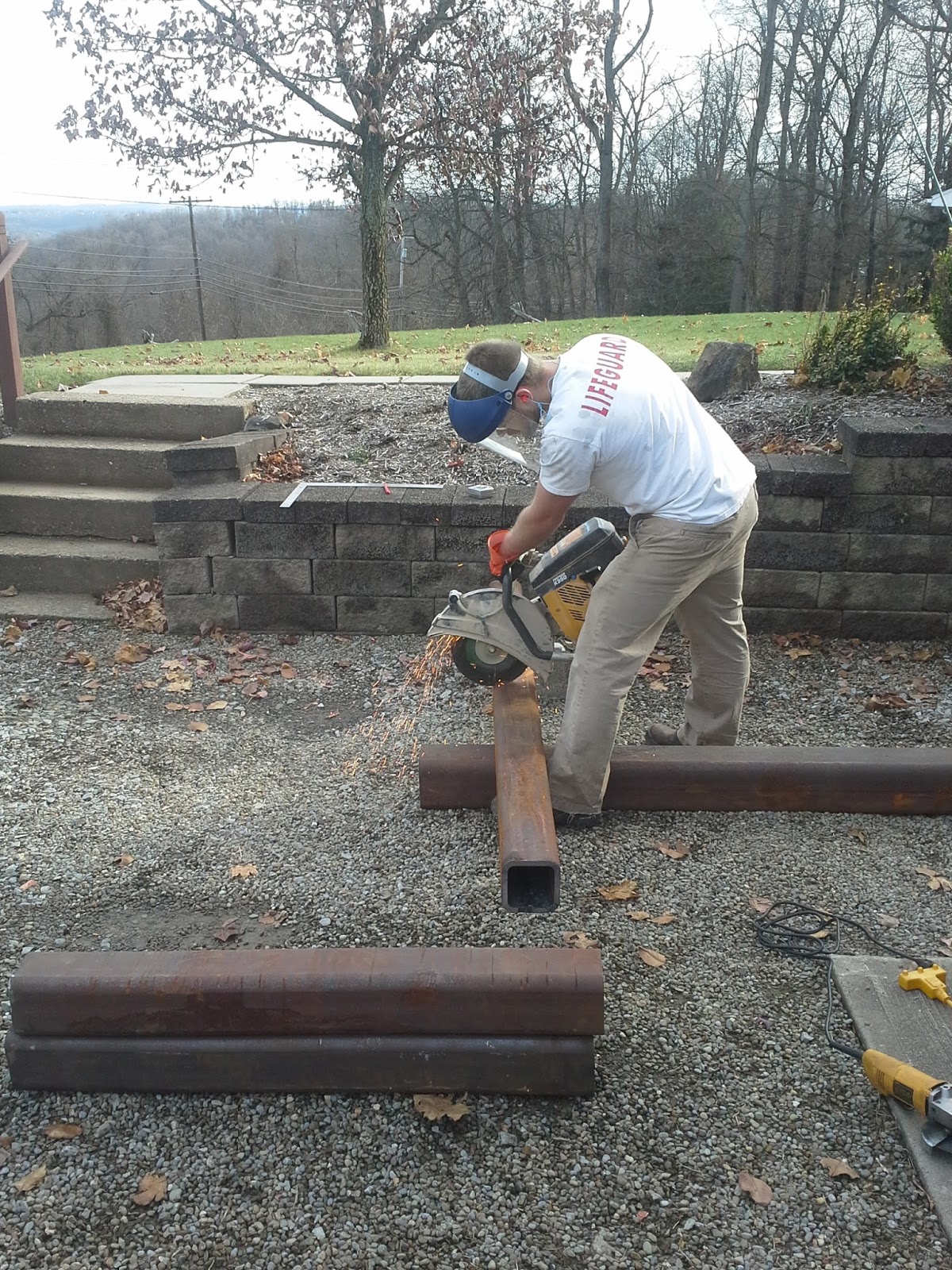
The first major step was to cut the square tube to length. I have limited resources, but Olson Landscaping supplied us with a gas powered cement saw. I purchased some 14" diameter cutoff wheels and we cut the beams to size. The biggest trick with this was to get the cut started. The high speed and large diameter of the wheel caused it to bounce and flex until we got deep enough into the steel.
After cutting the beams to length, we needed to notch each of the four 6x6 cross beams so that the 5x5 vertical beams would mate up. We used a 4.5" diameter cut off wheel and angle grinder to make these cuts.
In order to drill the holes necessary to connect the beams and have them be reasonably accurate, I co-drilled the two holes in the beam. I did this by centering the hole with a small center drill and then used a long 1/4 inch drill bit to drill through both sided of the beam. The holes in all the beams were mapped with the same template so that they would be as accurate as possible.
Stepping up the holes to 7/8" diameter proved to be a bit more difficult. My bench top drill press had a minimum speed of 600 rpm, but I needed to slow it down to 300 rpm to keep the larger drill bits from chattering. I did that by building the speed reducer shown below.
My bench top drill press also has limited horsepower. To complete the holes I couldn't just start with a 7/8 drill bit, but had to step them up. I finished the holes 1/32 oversize using a 29/32 drill bit. The sequence of drilling I used was:
- 1/4 inch center drill
- 1/4 inch short drill bit
- 1/4 inch long drill bit
- 1/2 inch drill bit
- 5/8 drill bit
- 3/4 drill bit
- 7/8 drill bit
- 29/32 drill bit
This sequence was completed for all 32 holes. It took some time, but with a cup of oil and a paintbrush we kept the drill bits cool and I only had to sharpen the 7/8 drill bit once.
Once the holes were drilled, I had to drill and tap four 5/16-18 holes to connect the wide flange beams to the cross beams. As with the other holes, I made a template so that each cross beam was identical. The drill press was used to complete the holes and each was hand tapped.

Mating holes were then drilled in the wide flange beams. In this case, I couldn't clamp the beams to the drill press as they were too heavy. Instead I moved the drill press to each of the sixteen hole locations.


I used a sanding wheel on my angle grinder to debur all the holes and then it was time to begin the assembly. I purchased all my fasteners from
McMaster Carr Supply Company.
The image below shows the 7/8" x 9 inch long bolts next to the 5/16 bolt used to hold up the beam. Note that the 5/16 bolt does not see load in service and only suspends the beam. Each beam has four bolts and will only see 110 lb of load.
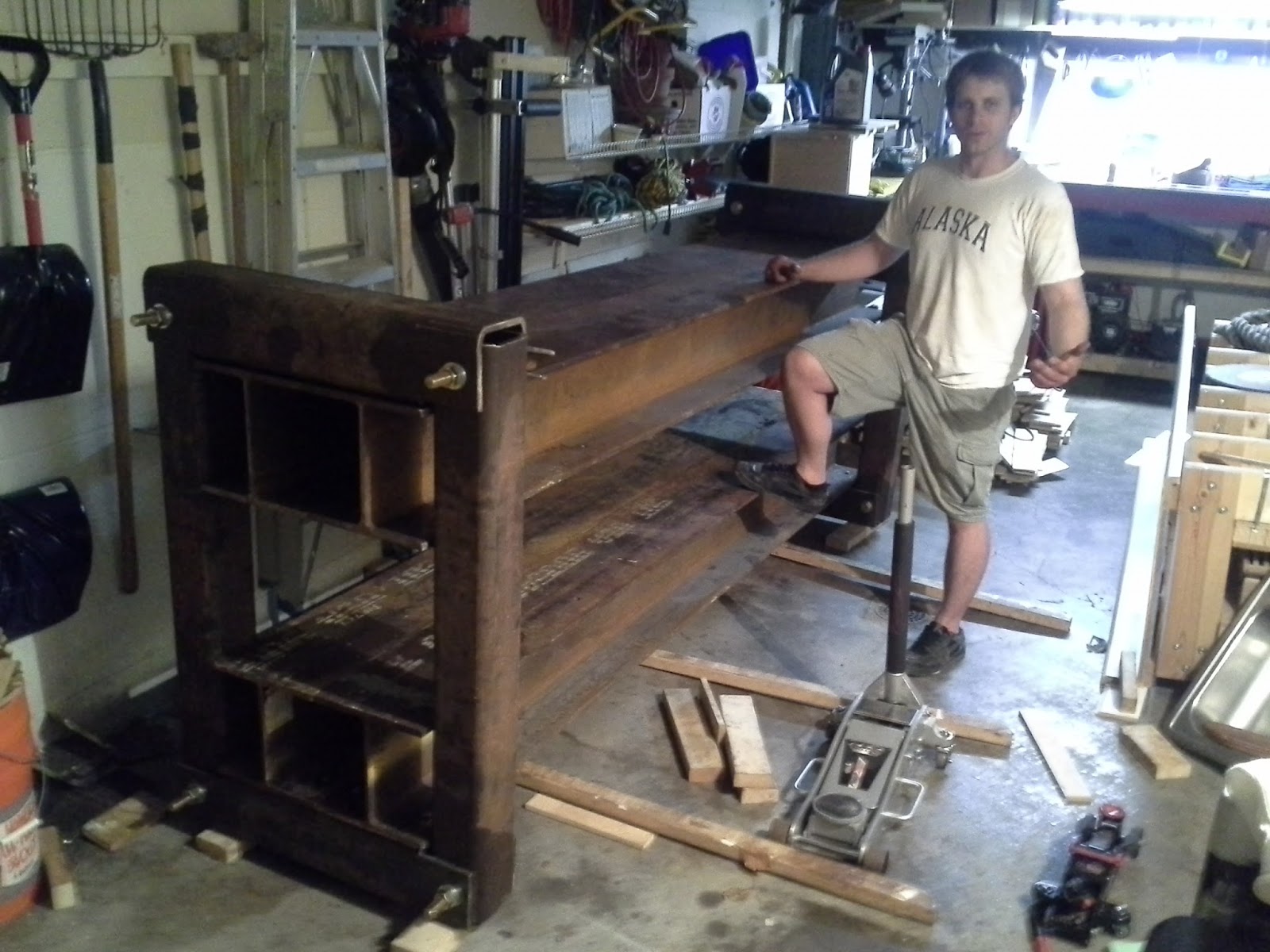
The image below shows the test fit-up of the braces; each brace has a weight of around 400 lb. The braces did go together the first time and none of the holes had to be tweaked. This is something of a miracle considering my rudimentary machining methods.
From this point, the rest of the press could be assembled. Note that the bolts stick out about three inches beyond the brace. This was done on purpose to ensure that only the shank of the bolt would see the bearing load due to the pressure. Loading on the threads would not be good for the bolt or braces.
A couple of jacks and some serious manpower was used to assemble the press. My original idea was to disassemble the press after test fit-up, wire brush it, and then paint it. After experiencing the amount of work to assemble it, I decided that the no-paint industrial look was more than adequate.
At this point the basic frame of the press is complete, but I still have to put the press on wheels, build a second air bladder, assemble my pressure regulating system, mount a working surface (MDF) to the press, and build a "ladder" to ensure even pressure distribution from the two air bladders.


.jpg)